 English
 Nederlands
 Français
 Deutsch
 Español
 Polski
 Русский
 العربية
 Română
Call us on +32 (0) 51 57 58 58 or contact us.
Sensor diverse
- New Thanks to our product knowledge and built-up relationships with manufacturers worldwide, we found the most reliable alternatives. Best price-quality.
 Availability: Immediately availableELE1.271.0049
 €300.30
Guide price excl. VAT
Equivalenten:
A3C1008780021, 31008780021, ELE1.271.0049, 12710049 - New Thanks to our product knowledge and built-up relationships with manufacturers worldwide, we found the most reliable alternatives. Best price-quality. Availability: Immediately availableELE1.271.0050 €327.60
Guide price excl. VAT
Equivalenten:
A3C1008790021, 31008790021, A3C1023720020, 31023720020, ELE1.271.0050, 12710050 - New Thanks to our product knowledge and built-up relationships with manufacturers worldwide, we found the most reliable alternatives. Best price-quality. Availability: Immediately availableELE1.274.0066 €45.47
Guide price excl. VAT
Equivalenten:
65.27421.0082, 65274210082, 65.27421-0082, 65.45960.6010, 65459606010, 65.45960-6010, 3108, 3108, ELE1.274.0066, 12740066 - New Thanks to our product knowledge and built-up relationships with manufacturers worldwide, we found the most reliable alternatives. Best price-quality. Availability: Immediately availableELE2.542.0118 €126.00
Guide price excl. VAT
Equivalenten:
ELE2.542.0118, 25420118, FEB197699, 197699, MB011.542.23.18, 0115422318, A0115422318, MB011.542.23.18/64, 0115422318/64, A0115422318/64 - New Thanks to our product knowledge and built-up relationships with manufacturers worldwide, we found the most reliable alternatives. Best price-quality. Availability: Immediately availableELE2.542.0119 €108.00
Guide price excl. VAT
Equivalenten:
ELE2.542.0112, 25420112, ELE2.542.0119, 25420119, FEB197704, 197704, MB011.542.24.18, 0115422418, A0115422418, MB011.542.48.18, 0115424818, A0115424818 - New Thanks to our product knowledge and built-up relationships with manufacturers worldwide, we found the most reliable alternatives. Best price-quality. Availability: Immediately availableELE2.905.0024 €52.96
Guide price excl. VAT
Equivalenten:
3013, 3013, 3128, 3128, ELE2.905.0024, 29050024, MB000.905.00.30, 0009050030, A0009050030, MB000.905.00.30/64, 0009050030/64, A0009050030/64 - New Thanks to our product knowledge and built-up relationships with manufacturers worldwide, we found the most reliable alternatives. Best price-quality. Availability: Immediately availableMB004.540.08.17€714.28
Guide price excl. VAT
Equivalenten:
MB004.540.08.17, 0045400817, A0045400817 - New Thanks to our product knowledge and built-up relationships with manufacturers worldwide, we found the most reliable alternatives. Best price-quality. Availability: Immediately availableMB010.542.08.18€457.81
Guide price excl. VAT
Equivalenten:
MB010.542.08.18, 0105420818, A0105420818 - Second-Hand Recovered from used trucks, we offer these parts. They are still in top condition and can last a long time. Availability: Immediately availableMB016.542.61.17.OCC €317.89
Guide price excl. VAT
Equivalenten:
MB016.542.61.17.OCC, 0165426117OCC, A0165426117OCC, MB016.542.61.17, 0165426117, A0165426117 - Second-Hand Recovered from used trucks, we offer these parts. They are still in top condition and can last a long time. Availability: Immediately availableMB017.542.06.17.OCC €325.42
Guide price excl. VAT
Equivalenten:
MB017.542.06.17.OCC, 0175420617OCC, A0175420617OCC, MB017.542.06.17, 0175420617, A0175420617 - Second-Hand Recovered from used trucks, we offer these parts. They are still in top condition and can last a long time. Availability: Immediately availableMB017.542.07.17.OCC €298.87
Guide price excl. VAT
Equivalenten:
MB017.542.07.17.OCC, 0175420717OCC, A0175420717OCC, MB017.542.07.17, 0175420717, A0175420717 - Nearly New Barely used and therefore a great opportunity! Buy these parts as if they were new, at advantageous prices. Availability: Immediately availableMB017.542.21.17.NNP €161.00
Guide price excl. VAT
Equivalenten:
MB017.542.21.17.NNP, 0175422117NNP, A0175422117NNP, MB009.542.81.18, 0095428118, A0095428118, MB017.542.19.17, 0175421917, A0175421917 - New Thanks to our product knowledge and built-up relationships with manufacturers worldwide, we found the most reliable alternatives. Best price-quality. Availability: Immediately availableMB405.542.07.18€270.23
Guide price excl. VAT
Equivalenten:
MB405.542.07.18, 4055420718, A4055420718 - Second-Hand Recovered from used trucks, we offer these parts. They are still in top condition and can last a long time. Availability: Immediately availableMB957.542.04.17.OCC €67.78
Guide price excl. VAT
Equivalenten:
MER957.542.04.17, 9575420417, A9575420417, MB957.542.04.17.OCC, 9575420417OCC, A9575420417OCC, MB957.542.04.17, 9575420417, A9575420417, MB990.542.26.00, 9905422600 ... - Second-Hand Recovered from used trucks, we offer these parts. They are still in top condition and can last a long time. Availability: Immediately availableMB960.542.02.17.OCC €178.10
Guide price excl. VAT
Equivalenten:
MER960.542.02.17, 9605420217, A9605420217, MB960.542.02.17.OCC, 9605420217OCC, A9605420217OCC, MB045.542.04.17, 0455420417, A0455420417, MB960.542.02.17, 9605420217 ... - New Thanks to our product knowledge and built-up relationships with manufacturers worldwide, we found the most reliable alternatives. Best price-quality. Availability: Immediately availableMB960.542.41.18€220.02
Guide price excl. VAT
Equivalenten:
MB960.542.41.18, 9605424118, A9605424118 - New Thanks to our product knowledge and built-up relationships with manufacturers worldwide, we found the most reliable alternatives. Best price-quality. Availability: Immediately availableMB967.542.07.17€200.28
Guide price excl. VAT
Equivalenten:
ELE2.542.0130, 25420130, MB967.542.03.17, 9675420317, A9675420317, MB967.542.03.17, 9675420317, A9675420317, MB967.542.03.17, 9675420317, A9675420317, MB967.542.07.17 ... - New Thanks to our product knowledge and built-up relationships with manufacturers worldwide, we found the most reliable alternatives. Best price-quality. Availability: Immediately availableVBA008.432 €215.18
Guide price excl. VAT
Equivalenten:
DAX1398467, 1398467, VBA008.432, 008432 - New Thanks to our product knowledge and built-up relationships with manufacturers worldwide, we found the most reliable alternatives. Best price-quality. Availability: Immediately availableVOI150.00334924
 €182.21
Guide price excl. VAT
Equivalenten:
15000334922, 15000334922, VOI150.00334922, 15000334922, VOI150.00334924, 15000334924, MB012.542.05.18, 0125420518, A0125420518 - New Thanks to our product knowledge and built-up relationships with manufacturers worldwide, we found the most reliable alternatives. Best price-quality. Availability: Immediately availableVOI153.00863710 €110.16
Guide price excl. VAT
Equivalenten:
H53.825812, 53825812, VOI153.00863710, 15300863710, VOIH53.825812, H53825812, VOIH53.825813, H53825813, MB009.542.19.18, 0095421918, A0095421918, MB009.542.19.18/64 ... - New Thanks to our product knowledge and built-up relationships with manufacturers worldwide, we found the most reliable alternatives. Best price-quality. Availability: Immediately availableZF0501.340.705
 €658.64
Guide price excl. VAT
Equivalenten:
81.32690.6072, 81326906072, 81.32690-6072, 81.32690.6080, 81326906080, 81.32690-6080, 0501340705, 0501340705, 0501340705ZF, 0501340705ZF, ZF0501.330.553, 0501330553 ... - New Thanks to our product knowledge and built-up relationships with manufacturers worldwide, we found the most reliable alternatives. Best price-quality.
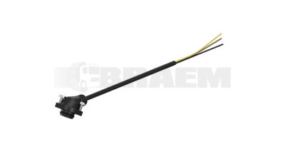 Availability: Request availability36.25402.6462€23.03
Guide price excl. VAT
Equivalenten:
36.25402.6462, 36254026462, 36.25402-6462, 36254026462, 36254026462, WES449.753.012.0, 4497530120 - Second-Hand Recovered from used trucks, we offer these parts. They are still in top condition and can last a long time.
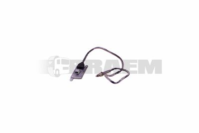 Availability: Request availability51.15408.0008.OCC €540.79
Guide price excl. VAT
Equivalenten:
51.15408.0008, 51154080008, 51.15408-0008, 51.15408.0008.OCC, 51154080008OCC, 51.15408-0008.OCC - New Thanks to our product knowledge and built-up relationships with manufacturers worldwide, we found the most reliable alternatives. Best price-quality.
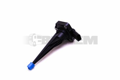 Availability: Request availability65.27421.6002€103.36
Guide price excl. VAT
Equivalenten:
65.27421.6002, 65274216002, 65.27421-6002, HEL6PR013680-031, 6PR013680031, 07P907660, 07907660, ELE1.274.0041, 12740041
Various sensors monitor parameters such as position, movement and distance. Depending on the type, they provide a switching signal, an analogue measured value or digital information to an ECU (Electronic Control Unit). An incorrect value can cause erroneous position readings or disrupt chassis control. Diagnosis must therefore include checks not only of the sensor, but also of the physical parameter being measured and the entire electrical circuit.
Depending on the vehicle specification, the following sensors may be fitted:
- Position sensor: detects the position of components such as a door, flap or selector mechanism for control and monitoring purposes.
- Ride height sensor: measures the position of the axle relative to the chassis to control the air suspension.
- Steering angle sensor: detects the steering angle and steering movement for stability control and driver assistance systems.
- Yaw rate sensor: measures the vehicle's rotation about its vertical axis for stability control.
- Acceleration sensor: measures longitudinal, lateral or vertical movement for chassis and stability control.
- Transmission speed sensor: measures the rotational speed of a transmission shaft for gearbox control and monitoring.
- Rain sensor: detects moisture on the windscreen to control the wipers automatically.
- Light sensor: measures ambient light to switch the lights on and off automatically.
- Parking sensor: detects nearby obstacles to assist with parking and manoeuvring.
Always identify parts using the vehicle's chassis number. Visual comparison or selection based on the model name alone is never sufficient. On MAN TGL, TGS and TGX or Mercedes Atego, Actros and Sprinter vehicles, connections, measuring ranges and signal characteristics can vary within the same vehicle series. For buses such as the MAN Lion's City and Mercedes Citaro, the chassis specification and system configuration also need to be considered.
Distinguish between potentiometric position sensors, inductive sensors, active Hall sensors and optical or ultrasonic sensors. Potentiometric position sensors use a resistive track to convert displacement into an electrical signal. Active sensors may provide an analogue voltage signal, a frequency signal or PWM (Pulse Width Modulation). An identical connector does not guarantee an identical pin assignment or output characteristic.
Check the nominal supply voltage, measuring range, temperature range and accuracy tolerance against the part specification. Thread size, insertion depth, sealing material and chemical resistance to substances such as transmission oil also determine suitability. For non-contact position sensors, the mounting orientation and air gap to the target are critical.
Moisture ingress, oxidised contact pins and broken wires at securing points often cause intermittent faults. Thermal ageing can cause readings to drift without immediately triggering a fault code. Contaminated sensing surfaces or damaged ride height sensor linkage rods can also produce plausible but incorrect signals. Multiple simultaneous sensor faults may indicate a shared power supply or earth fault.
- Read out fault codes and the associated operating data. Compare current measured values with the actual condition: for position sensors, for example, the displayed position must match the actual mechanical position.
- Inspect connector seals, terminal locking mechanisms, cable routing and mechanical mountings. Gently move suspect sections of wiring while recording the measured values.
- With the sensor connected, use a high-impedance multimeter to measure the supply voltage and the voltage drop across the earth connection. Many active sensors use a 5 V reference supply; always check the vehicle wiring diagram and never apply vehicle system voltage directly.
- Check analogue output signals across the operating range. Use an oscilloscope for pulse signals and momentary interruptions. Only measure resistance with the power off and the sensor disconnected, and compare the readings with the specified values for the relevant sensor position.
- Verify position and distance values using a suitable reference measurement in accordance with the manufacturer's instructions. Assess deviations against the manufacturer's tolerances before deciding to replace the sensor.
Secure the vehicle against unintended movement and support the chassis in accordance with the manufacturer's instructions when working on the ride height control system. Clean the mounting area without allowing dirt to reach the sensing surfaces. Use the specified seals and tightening torques; overtightening can distort sensor housings. Repair damaged connectors and cable fixings at the same time, otherwise the fault will recur.
After fitting, carry out a zero-point adjustment, calibration or relearn procedure if required, for example for ride height sensors. Then clear the fault codes and check the measured values during a functional test under representative operating conditions. This distinguishes a successful electrical repair from a mechanical or hydraulic cause that is still present.