 English
 Nederlands
 Français
 Deutsch
 Español
 Polski
 Русский
 العربية
 Română

Call us on +32 (0) 51 57 58 58 or contact us.
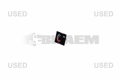
Pressure gauge

- Second-Hand Recovered from used trucks, we offer these parts. They are still in top condition and can last a long time.
 Availability: Immediately available

81.27410.6051.OCC
€219.00Guide price excl. VAT
Equivalenten:
81.27410.6051, 81274106051, 81.27410-6051, 81.27410.6051.OCC, 81274106051OCC, 81.27410-6051.OCC - Second-Hand Recovered from used trucks, we offer these parts. They are still in top condition and can last a long time.
 Availability: Immediately available
81.27410.6052.OCC
€219.00Guide price excl. VAT
Equivalenten:
81.27410.6052, 81274106052, 81.27410-6052, 81.27410.6052.OCC, 81274106052OCC, 81.27410-6052.OCC - Second-Hand Recovered from used trucks, we offer these parts. They are still in top condition and can last a long time.
 Availability: Immediately available
81.27410.6053.OCC
€219.00Guide price excl. VAT
Equivalenten:
81.27410.6053, 81274106053, 81.27410-6053, 81.27410.6053.OCC, 81274106053OCC, 81.27410-6053.OCC - New Thanks to our product knowledge and built-up relationships with manufacturers worldwide, we found the most reliable alternatives. Best price-quality.
 Availability: Request availability
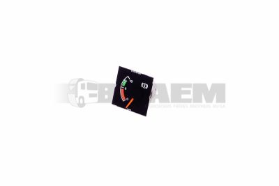
81.27410.6047
€356.17Guide price excl. VAT
Equivalenten:
81.27410.6040, 81274106040, 81.27410-6040, 81.27410.6040, 81274106040, 81.27410-6040, 81.27410.6047, 81274106047, 81.27410-6047, 81274106047, 81274106047 - New Thanks to our product knowledge and built-up relationships with manufacturers worldwide, we found the most reliable alternatives. Best price-quality.
 Availability: Request availability
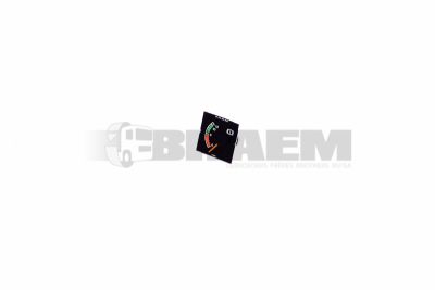
81.27410.6048
€287.86Guide price excl. VAT
Equivalenten:
81.27410.6041, 81274106041, 81.27410-6041, 81.27410.6041, 81274106041, 81.27410-6041, 81.27410.6048, 81274106048, 81.27410-6048, 81274106048, 81274106048 - New Thanks to our product knowledge and built-up relationships with manufacturers worldwide, we found the most reliable alternatives. Best price-quality.
 Availability: Request availability
81.27410.6052
€356.17Guide price excl. VAT
Equivalenten:
81.27410.6052, 81274106052, 81.27410-6052, 81274106052, 81274106052, 81.27410.6052.OCC, 81274106052OCC, 81.27410-6052.OCC - New Thanks to our product knowledge and built-up relationships with manufacturers worldwide, we found the most reliable alternatives. Best price-quality.
 Availability: Request availability
81.27410.6053
€356.17Guide price excl. VAT
Equivalenten:
81.27410.6053, 81274106053, 81.27410-6053, 81274106053, 81274106053, 81.27410.6053.OCC, 81274106053OCC, 81.27410-6053.OCC - Second-Hand Recovered from used trucks, we offer these parts. They are still in top condition and can last a long time.

- Second-Hand Recovered from used trucks, we offer these parts. They are still in top condition and can last a long time.
- Second-Hand Recovered from used trucks, we offer these parts. They are still in top condition and can last a long time.
- New Thanks to our product knowledge and built-up relationships with manufacturers worldwide, we found the most reliable alternatives. Best price-quality. Availability: Request availability
81.27410.6050
€356.17Guide price excl. VAT
Equivalenten:
81.27410.6050, 81274106050, 81.27410-6050, 81274106050, 81274106050, 81.27410.6050.OCC, 81274106050OCC, 81.27410-6050.OCC - New Thanks to our product knowledge and built-up relationships with manufacturers worldwide, we found the most reliable alternatives. Best price-quality. Availability: Request availability
81.27410.6051
€356.17Guide price excl. VAT
Equivalenten:
81.27410.6051, 81274106051, 81.27410-6051, 81274106051, 81274106051, 81.27410.6051.OCC, 81274106051OCC, 81.27410-6051.OCC
Pressure gauges in the instrument cluster display readings such as brake circuit pressure or engine oil pressure, depending on the vehicle's equipment. An incorrect reading can mask an actual pressure problem or cause unnecessary downtime. For MAN and Mercedes trucks, buses and vans, a reliable repair therefore starts by distinguishing between actual system pressure, pressure sensors, signal transmission and the dashboard display. Vans with hydraulic brakes generally do not have a brake circuit pressure gauge like vehicles with air brake systems.
Depending on the vehicle type, year of manufacture and equipment, the following pressure gauges or digital pressure displays may be fitted in the instrument cluster. Not every pressure reading is available as standard; some displays are only found on specific variants or with additional instrumentation.
- Brake circuit reservoir pressure gauge. Displays the available compressed air pressure in the individual brake circuits of trucks and buses with air brakes. A dual gauge can display both circuits.
- Brake application pressure gauge. Where fitted separately, displays the applied brake pressure during braking. This reading serves a different purpose from the reservoir pressure display.
- Engine oil pressure gauge. Displays the pressure in the engine lubrication system. Applicable to vehicles with a separate oil pressure gauge or digital pressure display; an oil pressure warning lamp is not a pressure gauge.
- Boost pressure gauge. Displays the intake air pressure in turbocharged engines. Depending on the version, either absolute pressure or gauge pressure is displayed.
- Transmission oil pressure gauge. Displays the oil pressure in a transmission circuit on specific transmissions and instrument configurations. This display is not fitted as standard on every automatic or automated manual gearbox.
- Tyre pressure display. With a suitable direct tyre pressure monitoring system, displays the measured pressure for each tyre on the dashboard display. Not every tyre pressure monitoring system displays individual pressure readings.
- Hydraulic working pressure gauge. Displays the pressure in a hydraulic working circuit on special-purpose vehicles or with additional instrumentation, for example for a tipper or crane. This gauge may also be located on the bodywork control panel rather than in the instrument cluster.
Mechanical pressure gauges may use a Bourdon tube and a direct compressed air connection. Dual brake pressure gauges display two separate brake circuits. Electrical pressure gauges process a pressure-dependent resistance signal or an electronic sensor signal; integrated displays often receive measured data via CAN (Controller Area Network). These versions are not necessarily interchangeable.
Always identify parts using the vehicle's chassis number. Visual comparison or selection based solely on the model name is never sufficient. Check the part number, nominal supply voltage, connector pinout, signal characteristics, scale graduations and warning functions. A scale of, for example, 0–12 or 0–16 bar does not indicate the permissible system operating pressure. The measuring range, overpressure resistance and accuracy class must meet the original specification.
For standalone dashboard instruments, check the mounting diameter, panel thickness, clamp mounting and available connection space. Relevant cab variants include MAN TGL C and LX, MAN TGX XLX and XXL, and Mercedes Actros Lang StreamSpace and Lang GigaSpace. For mechanical versions, the thread, sealing method and pipe connection must match; similar-looking fittings may have different thread pitches or sealing seats.
Jerky needle movement can be caused by pressure pulsations, intermittent electrical contacts or wear in the measuring mechanism. A needle that remains at zero may indicate a lack of pressure, an open sensor circuit or a seized needle drive mechanism. Condensate and contamination can restrict pneumatic supply lines; leaking fittings cause pressure loss. Corrosion, poor earth connections and damaged circuit board connections often cause temperature- or vibration-dependent errors in electrical instruments.
- Secure the vehicle. Secure the vehicle against rolling away. Do not continue driving if a brake pressure warning occurs; stop the engine if insufficient engine oil pressure is suspected. Only disconnect pneumatic connections once the relevant circuit has been depressurised in accordance with the manufacturer's procedure.
- Measure the actual pressure. Connect a calibrated reference pressure gauge with a suitable range to the specified test point. For brake systems, compare both circuits separately during pressure build-up, at stable pressure and during the specified operation. Only assess engine oil pressure at the specified engine oil temperature and engine speeds.
- Check the signal chain. Read out fault codes and live pressure readings. Measure the supply voltage and the voltage drop across the earth connection under load. Check resistive sensors with the power off against their pressure-resistance characteristic; measure electronic output signals according to the wiring diagram. Do not arbitrarily short-circuit sensor wires to test the needle.
- Assess the reading. Compare several measurement points with rising and falling pressure to identify zero-point errors, hysteresis and non-linearity. Check deviations against the manufacturer's tolerances. Correct diagnostic values combined with an incorrect dashboard reading point towards a fault in the instrument, communication or configuration.
Only replace a pressure gauge once the supply, wiring and pressure sensors have been confirmed to function correctly. Use the specified seals and tightening torques; prevent sealant from entering compressed air passages. Rectify cable chafing and moisture ingress before installation. An integrated electronic display may require variant coding.
After installation, check connections with a leak detection solution where permitted. Repeat the comparison with the reference measurement and test the illumination, dimming function and pressure warnings in accordance with the manufacturer's procedure. Technical support from Braem during removal and installation helps prevent connection errors.